Lately I have renewed my interest in wideband radio. The question is, what is possible now? Turns out, it’s all in the amplifier.
Texas instruments makes a very interesting wideband radio frequency (RF) amplifier. It is called the THS3202. There is a saying in radio, “DC to daylight” to describe this kind of part. The 3202 goes from 100 kHz to 2 GHz, not quite daylight, but pretty close.

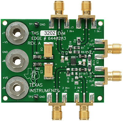
THS3202 Wideband RF Amplifier -- Texas Instruments
That is sixty-five times more bandwidth than the Hammarlund of the previous article. That’s a lot. The 3202 weighs much less than a gram. That’s a little. You can see it in the center of the board above.
Here is a circuit showing the THS3202 in action:

3202 Amplifier in Action -- Bruce Carter TI
Finding the Needle in the Haystack
There are three ways of teasing a given signal out of the haystack of broadcasting and noise.
1) Resonate incoming RF through LC tank circuit to select a specific signal.
2) Multiply all incoming RF by a frequency you choose and generate.
3) Bandpass filter all incoming RF to amplify the desired frequencies and quench the rest.
Most radios use methods 1 and 2, heterodyning to demodulate the incoming signal. Here we focus on method 3, homodyning, made possible by advances in amplifier technology...
Filtering
Trump, Stitt and Bishop of Texas Instruments have created a program called FilterPro™ that enables the accurate specification of filter banks for a wide range of frequencies. Low-Pass, High‑Pass and Band-Pass filters can be designed using Butterworth, Bessel, Chebychev and other common filter paradigms. FilterPro™ allows cascading stages of bandpass filtering that use identical components, except for the filter capacitors. As a quick example, consider the following two‑ pole filter centered at 500 MHz:

Two Pole Bandpass Filter created using FilterPro™
An iterated use of the program produces the following range of component values in a five-pole bandpass filter:

Capacitor Values Required for Wideband Filter Tuner

Capacitor Values Required for Wideband Filter Tuner
Five stages of the filter shown above enables a very wideband filter to be created that can serve as a radio tuner. From the graph we can see that the bandpass filter not only filters, it amplifies the signal of interest by 40 decibels (dB), or a factor of 10,000.
A Switched Variable Capacitor
“Back in the day” variable capacitors with consecutive ganged stages were used to address the tuning problem. They looked like this:

Air Variable Capacitor from Wikipedia
Modern versions of such capacitors have a range of capacitance from 15 picofarads to 384 pF. Synchronizing 10 instances of 15000 pF each would require 390 such units.
The trouble is that for each section of our five pole bandpass filter, we required two capacitors whose values can range from 1 pF to 15000 pF, that is, five decades of variation. A coordinated five pole array requires ten wideband variable capacitors operating in near-perfect unison. Accomplishing this with combinations of mechanically ganged variable capacitors is not practical.
This paper explores the creation of a variable wideband capacitor constructed using arrays of surface mount capacitors and solid state relays.


Novacap Capacitors and Teledyne RF Relay
The questions are:
· What topology of array?
· What form of switching?
A useful design would require.
Clearly the equivalent series resistance (ESR) of the switched capacitor should be as low as possible to maintain the idealized properties of a capacitor.
Two solutions come to mind. Both give rise to interesting mathematical analysis. We will start with the simplest first.
Note” The term “array” will be used to talk about the ensemble of capacitors used to create a single variable wideband capacitor. The term “bank” will be used to talk about a synchronized set of such variable wideband capacitors.
Point of Clarification
A Simple Decade Array
Consider an abacus like arrangement:

A Switched Variable Capacitor from 0 – 99,999 pF with 1 pF Steps
This capacitor would require 5 columns for each of the five decades. Each column would require 9 capacitors to represent the digits in each decade. The result would be a variable capacitor of 0 – 99,999 pF in 1 pF steps. Now obviously lead capacitance would make absolute values below 5 pF difficult to obtain, but increments of 1 pF could be realized with this device. This bank requires 45 capacitors and 45 switches to accomplish this task. With surface mount technology it would be the size of a postage stamp.
The question is finding those values of capacitance.


